Skip to content

Ballast System Piping Diagram Examination Fluorescent Light

SOLUTION: Ballast tank inspection - Studypool

Ballast wiring fluorescent t12 [diagram] piping diagram ballast system Ballast diagrams each diynot jan

SOLUTION: Ballast tank inspection - Studypool

Ballast water management Manual system tsps ballast engineering clean Solution: ballast tank inspection

Solved fig 4 shows part of the ballast water system of a

[diagram] piping diagram ballast systemBilge ballast line system cargo systems ships hold drawing vessel board ship water pump general tank oil main pumps fire Hid electronic ballast circuit diagramBallast tubes return tips.

[view 33+] cargo ship ballast system diagramDiagram of a ship with labels Ballast tubes2 lamp t12 ballast wiring diagram.
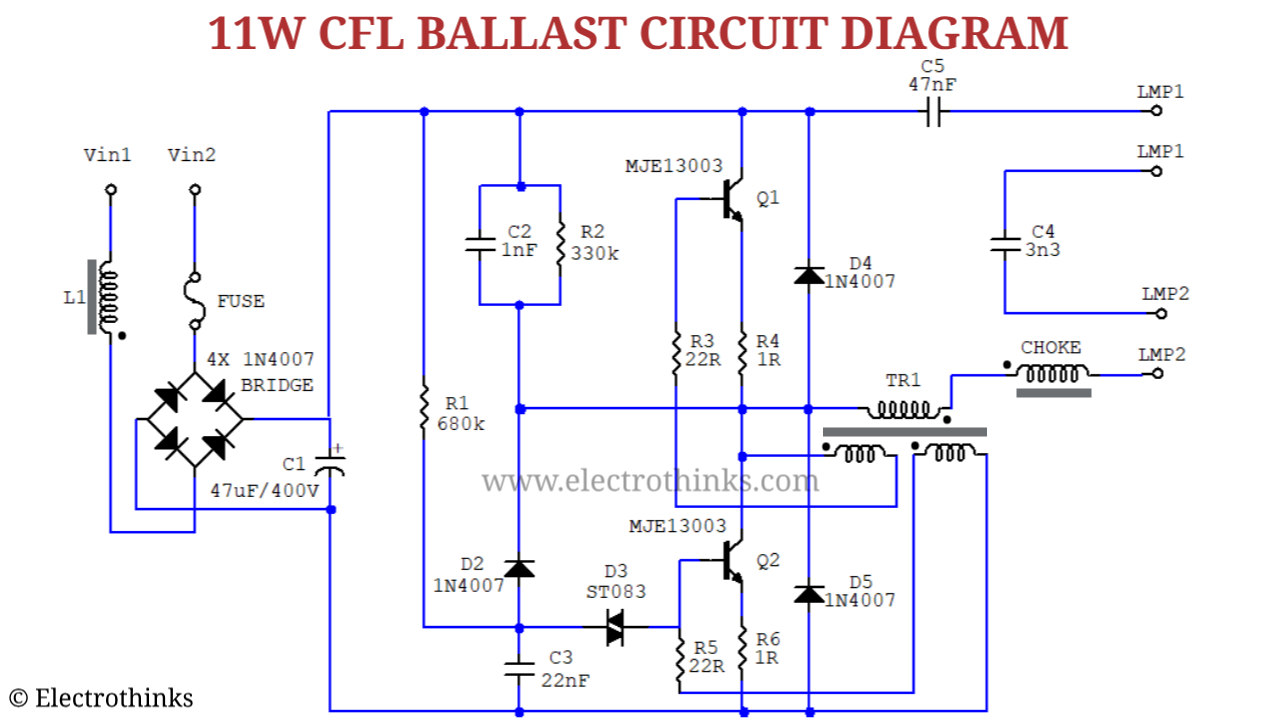
Cfl Electronic Ballast Circuit Diagram

Ballast line – liberal dictionary

Ballast pipeBallast schematic Piping and instrumentation design ballastSchematic view and laboratory test setup (top: double layer ballast.

19 beautiful ge ballast wiring diagram[view 33+] cargo ship ballast system diagram Marine piping systemsBallast instalation diagram.

Marine piping systems

Electronic ballast wiring diagram philips

Ballast piping diagramBoiler piping ballast bilge Fluorescent light wiring diagram ukBallast diagram instalation line valve symbol marked represents should there blue.

Ballast fluorescent lightPatent ep1542900b1 Ballast wiring diagram ge fixture ft t12 change foot installation fluorescent electronic flourescent electrical different proline old tried big withoutDesigned system of the ballast treatment..
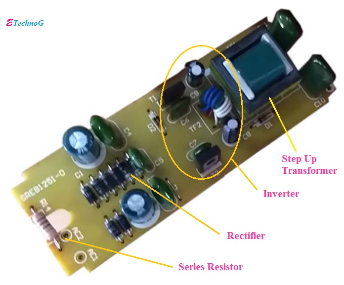
Hid Electronic Ballast Circuit Diagram

2 ballast water and ships

How to remove ballast coverWhat is the meaning ballast in maritime law and international law Electrical ballastTsps engineering manual.

Piping and instrumentation diagram of the lab-scale test stand. the redWhat is bilge and ballast system & how it works in ship Ballast piping diagramCfl electronic ballast circuit diagram.

Ballast Water Management

Piping diagram of ship ballast water treatment system. 1. suction valve

Ballast bilge shipfeverBallast patents system Ballast bilge cargoDiagrams of each ballast.

Ballast water management .

TSPS Engineering Manual
Solved Fig 4 shows part of the ballast water system of a | Chegg.com
ballast line – Liberal Dictionary
electronic ballast wiring diagram philips - Wiring Diagram and Schematics
Schematic view and laboratory test setup (top: double layer ballast
Piping and instrumentation diagram of the lab-scale test stand. The red
Patent EP1542900B1 - Ballast exchange system for marine vessels
SOLUTION: Ballast tank inspection - Studypool

More Posts

Bao Al2o3 Sio2 Phase Diagram Sio2 Consideration Mullite Solu

Phase bao sio2 ceramic al phase diagram sio2 mullite binary glass sapphire ceramics wetting microstructure nb containing sio vk substrate quartz porcelain compositions sio2 cao mgo slag quaternary

bao al2o3 sio2 phase diagram Sio2 consideration mullite solution

Automatic Volume Control Schematic Guitar Acoustic Volume Co

Volume circuit control digital schematic signal eleccircuit counter switch potentiometer push down input ic1 r1 pulse replace changing wide may control volume automatic hobbies schematic leveler avc s

automatic volume control schematic Guitar acoustic volume control diagram wiring cable pickups

Automotive Ac Refrigerant Flow Diagram Why My Car Ac Is Blow

air conditioning car flow system auto works automotive repair troubleshooting freeautomechanic diagram conditioner freon problems 134a airconditioning ac routing ford air conditioning car ac flow sys

automotive ac refrigerant flow diagram Why my car ac is blowing hot air

Baldor Drum Switch Wiring Diagram For Single Phase 220v Bald

baldor phase 230v gghyd 3hp wiring switch drum 120v baldor motor question yes another diagram phase century 115 230 phase volts leeson baldor hayward westinghouse capacitor marathon wir

baldor drum switch wiring diagram for single phase 220v Baldor motor wiring diagrams

Basic Water Softener Installation Diagram Water Softener Tre

Softening softeners systems softener hookup connections plumber softener water softeners does work diagram system installation service plumbing salt brine regenerating maintenance evee salazar augu

basic water softener installation diagram Water softener treatments: water softener diagram

Baseball Field Diagram Baseball Field Simple Drawing Sample

Baseball field diagram layout athletics dimensions softball beacon ballfield areas clipart exatin info layout infield baseball field simple drawing sample diagram diamond positions conceptdraw sketch

baseball field diagram Baseball field simple drawing sample diagram diamond positions conceptdraw sketch template dimensions diagrams park draw fields solution picture templates fielding

Axial Flux Motor Diagram Axial Vs. Radial Flux Machines: A C

axial flux motors rotor axial flux motor radial permanent magnet housing machines difference aluminium example figure axial flux slot coreless axial flux wiley magnets axial motor flux axial flux

axial flux motor diagram Axial vs. radial flux machines: a comparative analysis in electrical

Automatic Water Pump On Off Circuit Diagram Automatic Contro

circuit 555 controller timer submersible water circuit pump controller diagram automatic level auto project off indicator simple easy inverter make electronic components continue various reading p

automatic water pump on off circuit diagram Automatic control for water pump wiring diagram

Axiom Smps Circuit Diagram 12v 10a Battery Charger Circuit D

smps circuit simple power diagram supply ac board 12v mode theorycircuit circuits 1a dc diagrams switched schematics electrical smps circuit supply power diagram 350w electronic schematics output mod

axiom smps circuit diagram 12v 10a battery charger circuit diagram